Power conditioner repair
Furman PL-Plus E Series II Repair: Finding the Fault Behind a Silent Relay
By Repair Lab · Kangaroo Flat, Bendigo ·
A power conditioner is easy to overlook when it is doing its job. It sits in a rack, distributes power and helps protect the equipment connected to it. When its own electronics develop a fault, however, an entire rack can be left without power.
This Furman PL-Plus E Series II came to Repair Lab in Kangaroo Flat, Bendigo, with a fault in its power and relay-control circuitry. The relay was not switching on, even though testing showed that the relay itself worked. The investigation led to a small film capacitor in the control supply—a component with a much bigger influence on the unit than its size suggests.
The repair involved tracing the supply circuit, checking capacitor values, investigating abnormal voltage and heat during diagnosis, replacing the faulty dropper capacitor, and adjusting the overvoltage shutdown point. It is a useful example of why a relay that will not click is only the beginning of a diagnosis.
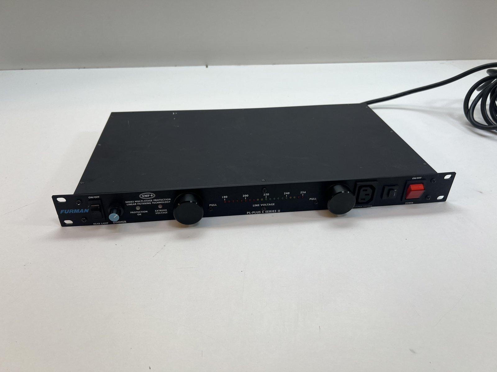
What does this Furman power conditioner do?
The PL-Plus E Series II is the 220–240 V version of Furman’s rack power conditioner. Its features include power distribution, SMP+ surge protection, LiFT filtering, a front-panel LED voltage display and retractable rack lights. It also has an extreme-voltage shutdown function that can disconnect the outlets when the incoming voltage is too high. [1]
For an owner, the distinction between those functions matters. A fault in the relay-control supply can prevent power from reaching connected equipment even if the relay contacts and other sections of the unit remain serviceable. The symptoms need to be traced to the circuit responsible for them.
This model does not regulate a fluctuating input back to a fixed 230 or 240 V output. Filtering, surge suppression and overvoltage disconnection perform different jobs from voltage regulation. [1]
The starting point: a working relay that would not switch on
Our initial job notes recorded a faulty power supply, a relay that tested good, and a suspicion that the circuit commanding the relay was not operating correctly. That narrowed the investigation. Replacing the relay simply because it was silent would have missed the fault elsewhere on the board.
The fitted relay is a Song Chuan 832A-1A-C with a 48 V DC coil. A relay contains two electrically different parts: the coil that operates its mechanism and the contacts that switch the load. Establishing that the relay works does not establish that the surrounding circuit is supplying the voltage and current needed to operate it.
At this stage, several explanations were still possible: a missing or inadequate control supply, a problem in the relay driver, or a protection circuit preventing activation. The task was to distinguish between those possibilities using the circuit connections and measured behaviour.
Looking inside the protection board
With the cover removed, the mains filtering and protection assembly was accessible alongside the front-panel electronics, wiring and lighting assemblies. The relay sits on the protection board near the incoming mains connections and the components supplying its control circuitry.
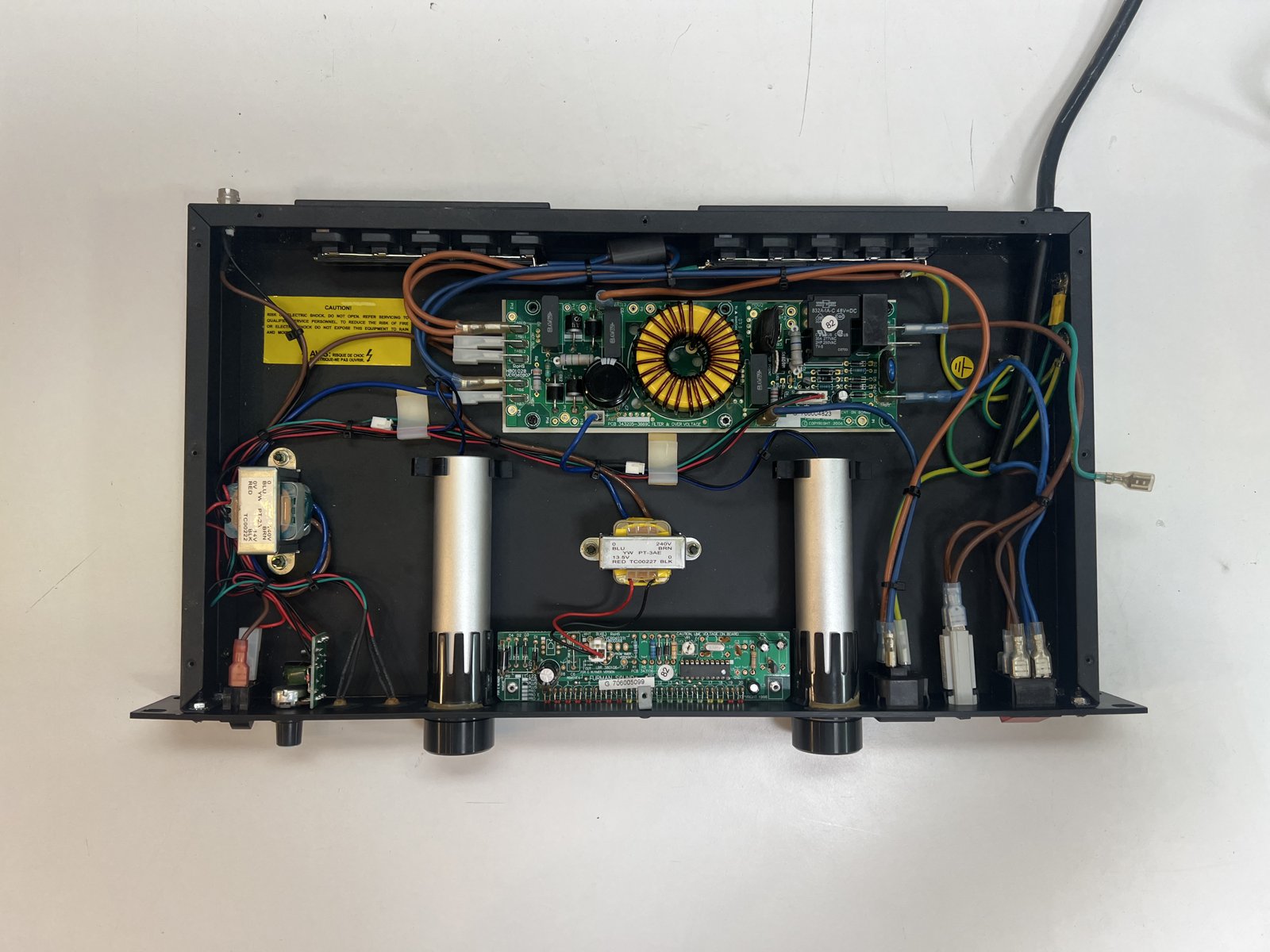
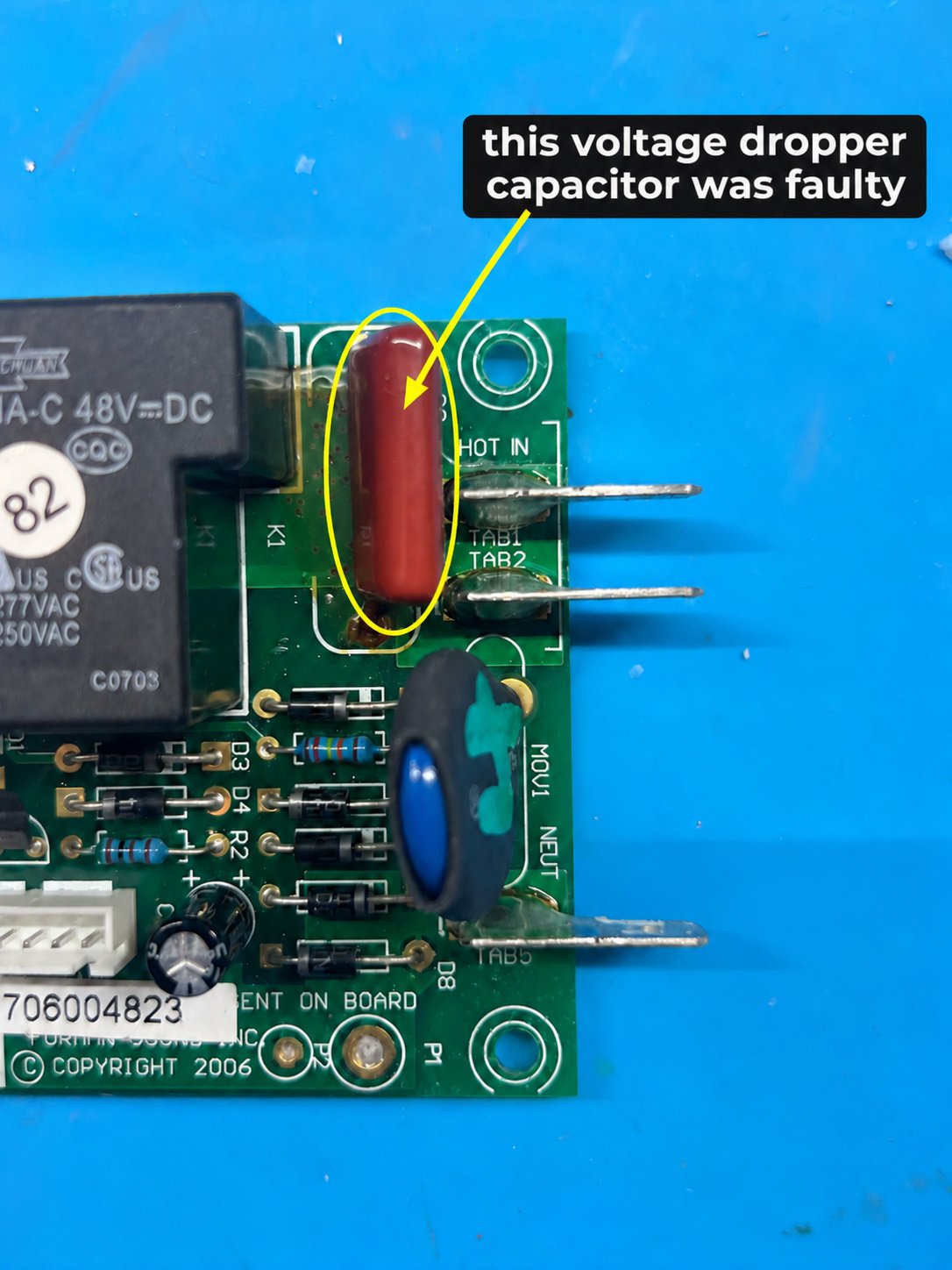
Tracing the connections identified a film capacitor running from the incoming active supply towards the bridge rectifier. That position explained its role: it was part of a capacitive dropper power supply. It was not merely another capacitor across the mains for interference suppression.
The original red/orange component was marked “F.27K MD 400V”. The nominal capacitance identified during the repair was 0.27 µF, equivalent to 270 nF. The K marking indicates a ±10% capacitance tolerance. That nominal value became an essential reference for the replacement.
How a small capacitor can stop the whole unit
A capacitive dropper uses a capacitor’s opposition to alternating current—its reactance—to limit current into a small supply. Rectification and the downstream circuitry then provide DC for the load. This approach can supply low-power circuitry without a conventional transformer in that particular supply path. [2]
Its behaviour depends on capacitance and frequency. At a fixed mains frequency, a larger capacitance has lower reactance and allows more current. A smaller capacitance has higher reactance and allows less. The dropper therefore helps determine the current available to the circuit; it does not independently guarantee a fixed DC output voltage. [2]
That gives the dropper capacitor a direct connection to the symptom we were investigating. If the control supply cannot deliver what the relay circuit needs, a perfectly functional relay can remain inactive. The investigation of this unit identified the dropper capacitor as the faulty component.
Film capacitors can lose capacitance without an obvious rupture or burn mark. Manufacturer guidance describes capacitance loss as a potential cause of failure in capacitive supplies. That is a general failure mechanism, rather than a measured percentage of deterioration for this particular capacitor. [3]
Why matching the capacitance mattered
During diagnosis, a temporary replacement marked “105K 400V” brought the relay into operation, but abnormal heating and supply voltages were then observed. The marking was significant: 105 represents 1 µF, which is substantially larger than the original 0.27 µF.
The difference is approximately 3.7 times the capacitance. A simple reactance calculation illustrates its size: at 50 Hz, 0.27 µF has a reactance of about 11.8 kΩ, while 1 µF is about 3.18 kΩ. These are component calculations, not measurements of the Furman’s output current or a complete model of its rectifier circuit.
The relay switching was useful evidence that the circuit could activate, but the accompanying heat and voltage readings showed that this temporary substitution was unsuitable as a finished repair. A larger capacitance in this position changes the supply’s operating conditions. It is not an upgrade simply because the relay now clicks.
This was also why we distinguished capacitance from voltage rating. Increasing a component’s voltage withstand rating, where otherwise appropriate, is a different decision from changing its capacitance. In a dropper supply, the latter changes a central part of how the circuit operates.
Investigating the abnormal DC voltage and heat
The diagnostic discussions recorded readings around 160 V DC at the 47 µF capacitor position, with subsequent readings around 92 V and 90 V as the circuit heated. The capacitor in that position, C3, was identified as 47 µF, 63 V. Some measurements were taken with that capacitor removed, so they should not be treated as a single stable, loaded operating voltage.
Even with that distinction, the readings demanded attention. A supply node intended to operate with a 63 V capacitor cannot be accepted as healthy on the basis of a relay click when testing is also producing much higher voltages and excessive heat. The conditions of the test and the cause of the abnormal behaviour had to be considered together.
Two electrolytic capacitors were measured during the investigation:
| Component | Recorded capacitance | Recorded ESR |
|---|---|---|
| 47 µF, 63 V capacitor (C3) | 42.76 µF | 0.86 Ω |
| 100 µF, 400 V capacitor | 94.87 µF | 0.17 Ω |
These readings were diagnostic observations, not final acceptance results. The 100 µF capacitor was also reported as hot to the touch, and replacement of both electrolytics was discussed. A capacitance or ESR reading alone does not explain every aspect of a capacitor’s behaviour under working voltage, nor does it remove concern about a component that has been exposed to abnormal operating conditions.
The broader lesson from this stage was to examine the supply as a circuit. The dropper, rectifier, capacitors and control load interact. Looking at only one reading—or only at whether the relay moves—can give an incomplete picture of the fault.
Replacing the faulty dropper capacitor
The faulty dropper capacitor was replaced, as shown in the repair photograph below. The replacement occupies the same functional position beside the relay, between the incoming supply and rectifier section.
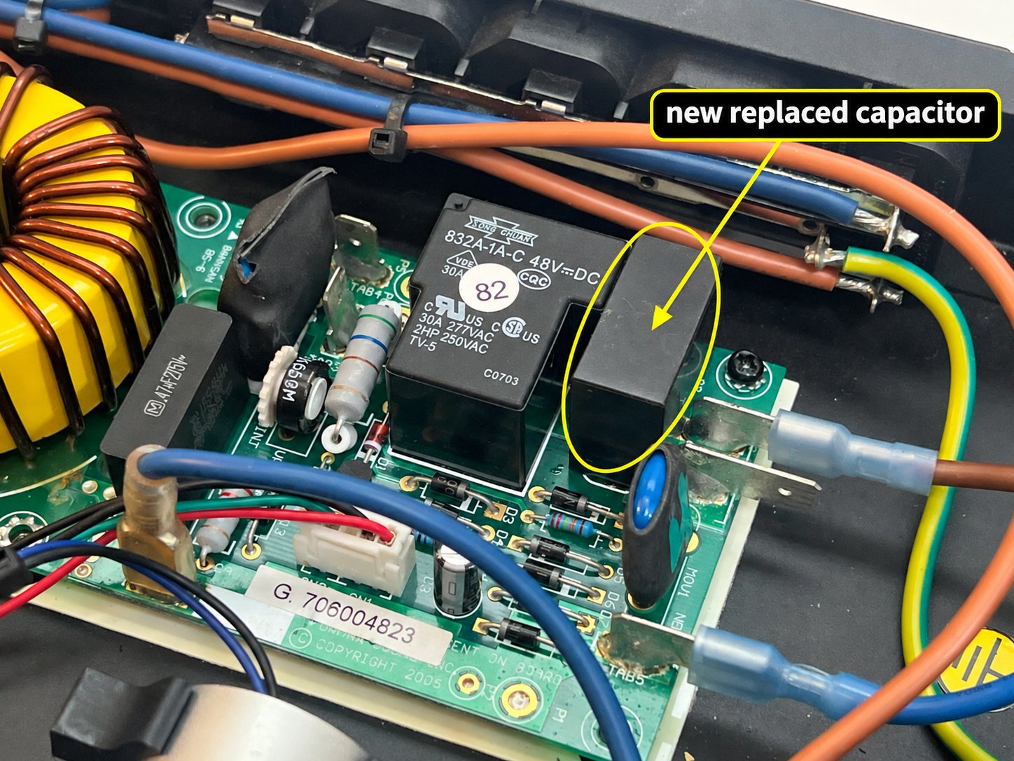
Selecting a capacitor for this position involves more than finding a similar-looking package or a high printed voltage. Capacitance, AC operating suitability, lead spacing and the manufacturer’s approval for continuous series-to-mains use all matter. A general interference-suppression classification alone does not establish suitability for every capacitive supply application. [3]
Checking the overvoltage shutdown
The later bench work included adjusting the relay’s overvoltage cutoff while monitoring the input with a digital multimeter. The recorded setting for this unit was approximately 265 V AC.
That check concerns sustained excessive input voltage. The shutdown circuit disconnects power through the relay when its threshold is reached. It is separate from the circuitry dealing with brief transient spikes, and the two functions should not be confused. [1]
The Furman-authored Series II manual consulted for this account lists 260–265 V for the E-version shutdown range. The 265 V figure here is the bench setting recorded for this individual repair, rather than a universal adjustment instruction for every Furman model or board revision. [1]
Testing that the relay can release at an excessive input voltage adds information that a normal startup test cannot provide. It addresses a protection function central to the purpose of the unit. It does not, by itself, constitute a laboratory test of surge suppression or verify every aspect of the conditioner’s performance.
What this repair established
The investigation moved from a silent relay to a fault in the supply supporting its operation. The relay had already tested good; the dropper capacitor was identified as faulty and replaced. Relay activation was demonstrated during diagnosis, and the later overvoltage cutoff adjustment was recorded at approximately 265 V AC.
Those findings explain why tracing the circuit was worthwhile. The largest or most visible component was not automatically the part responsible for the failure. A small capacitor in the control supply could prevent an otherwise functional switching component from operating.
They also show the value of following up an apparent improvement. A device beginning to switch again is useful progress, but abnormal heat or voltage remains a finding to resolve. Repair decisions need to account for the conditions around a component as well as the component itself.
Component-level repair in Bendigo
For owners of studio, live-sound and other rack equipment, a failed power conditioner can interrupt the use of everything connected to it. Understanding whether the problem lies in a switching component, its supply or its control circuit helps establish what repair is actually required.
This Furman repair is an example of the investigation behind a component-level repair at Repair Lab: checking the original symptom, tracing the relevant circuit, comparing component values, interpreting the measurements and examining the protection behaviour.
If you have a Furman power conditioner or other electronic equipment that has stopped working, contact Repair Lab in Kangaroo Flat, Bendigo, through repairlab.com.au to discuss an assessment.
Technical references
- Furman Sound, Series II owner’s manual (Furman-authored manual reproduced by ManualMachine), especially operation and shutdown sections.
- TDK Electronics, Everything for capacitive power supplies from a single source.
- Würth Elektronik, ANP124a: Capacitive Power Supplies—Selecting the Input Capacitor, 16 February 2024 (manufacturer application note hosted by Mouser).