PCB repair log
When a $2,000 industrial mixer repair turned out to be one capacitor
A maintenance electrician from a local food manufacturer brought in the DC braking controller from a large industrial mixer. The mixer brake had become unreliable, and the replacement controller was going to cost around $2,000 before retrofit work.
The fault
The mixer had stopped operating correctly because the braking system had become unreliable. Sometimes the motor brake would operate normally. Other times the brake would remain applied instead of releasing after a few seconds.
The electrician had already traced the machine fault back to this control board, so the next step was to find out whether the original controller could be repaired rather than replaced and retrofitted.
What the brake controller does
Despite the name, this system does not use a mechanical brake. The mixer uses a large AC induction motor. When the machine is stopped, the controller disconnects the normal AC supply and briefly injects DC current into the motor windings.
That creates a stationary magnetic field inside the motor. The rotor is still spinning through that magnetic field, so braking torque is produced and the motor stops much faster than it would if it were left to coast.
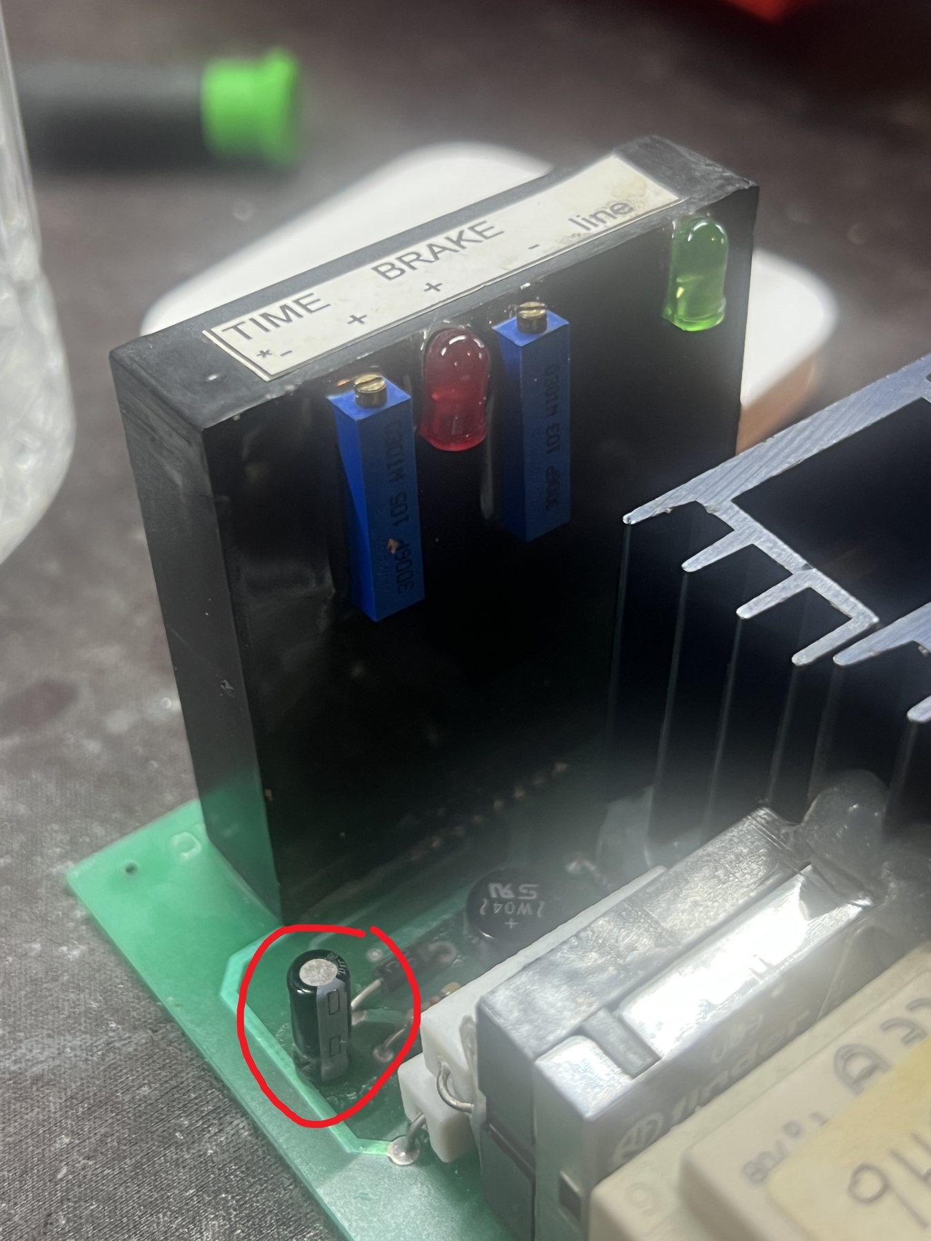
- BRAKE adjusts the strength of the braking current.
- TIME determines how long the braking current is applied.
Once the timer expires, the braking current should switch off. In this case, that last part was not happening reliably.
Testing the timer circuit
The controller had a separate low-voltage control section operating at approximately 21 to 24 volts. Initially, the timer circuitry itself looked suspicious. If the timer was failing, it could explain why the brake remained enabled.
Instead of immediately dismantling the timer module, we isolated its power supply and fed it approximately 21 V DC from an external bench supply.
Suddenly, it worked perfectly. The brake output activated, the timer ran, and a few seconds later the output released exactly as it should.
The timer was not the problem. Its power supply was.
Time to get the oscilloscope out
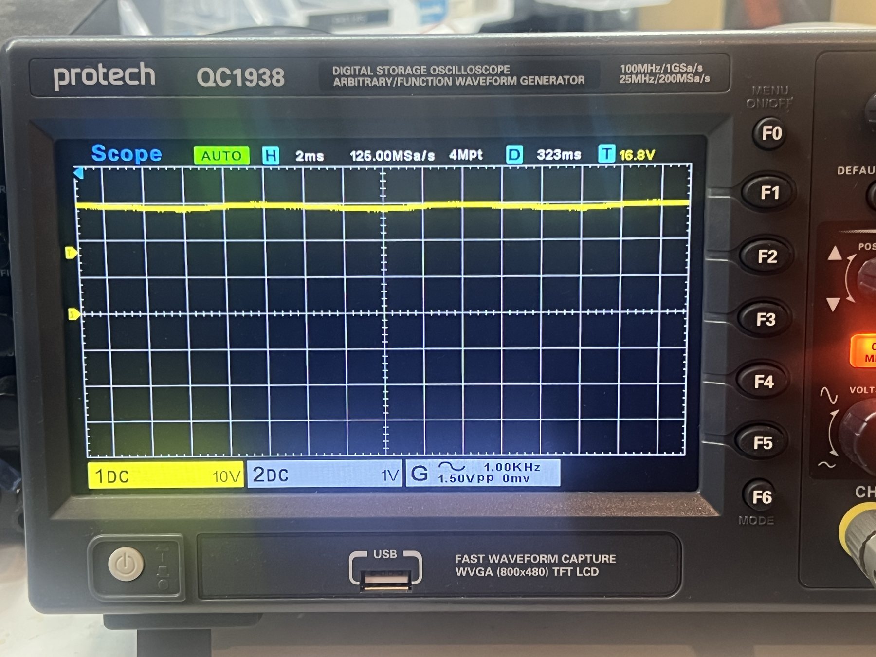
Measuring the supply with a multimeter showed voltage present, but a multimeter only gives part of the story. We connected an oscilloscope to the DC side of the bridge rectifier.
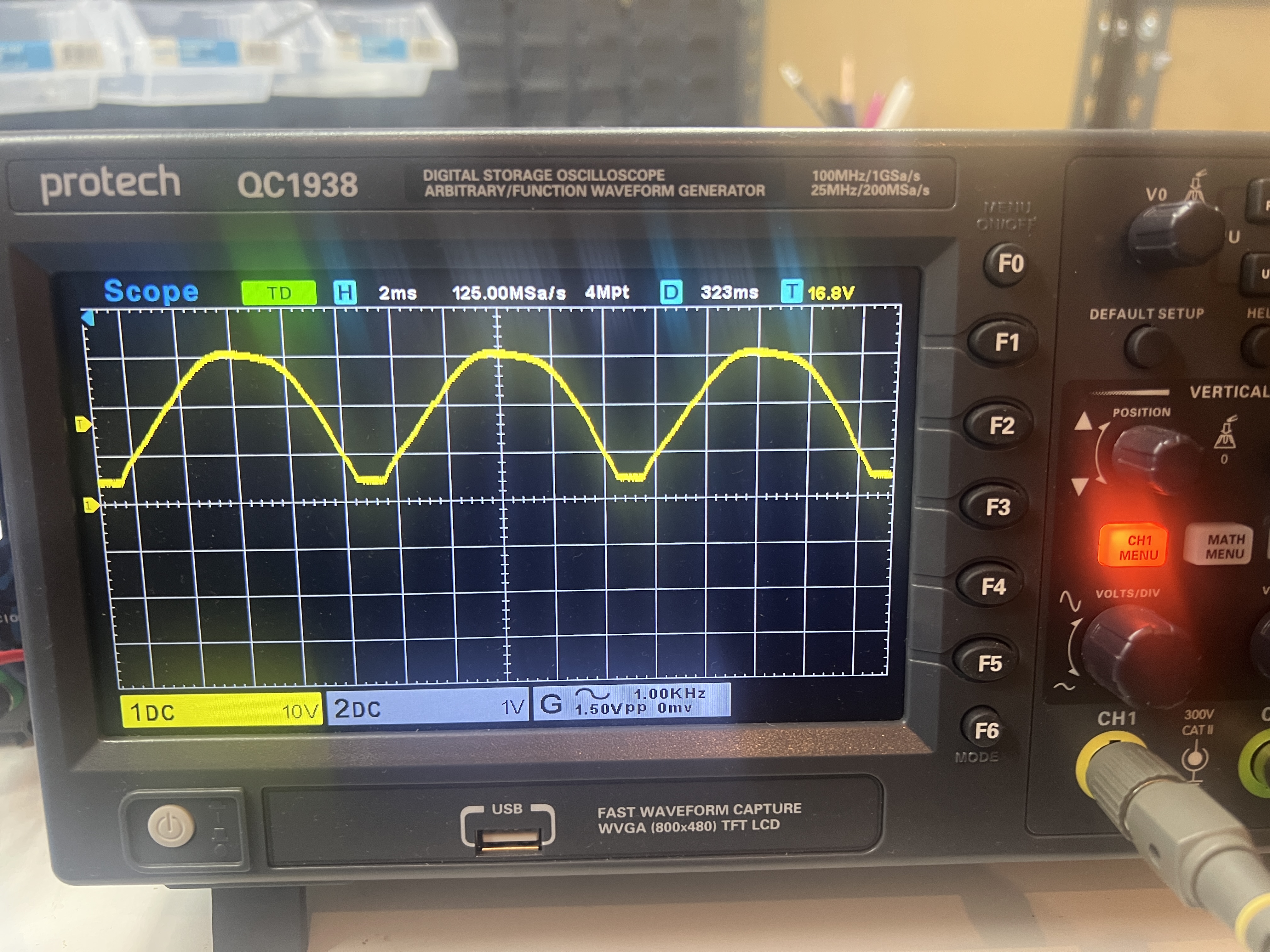
Instead of the supply remaining reasonably constant between each 100 Hz rectified peak, the voltage was dropping dramatically. The timer electronics were effectively being powered by a badly pulsating supply.
That explained the intermittent behaviour. Sometimes the timing circuit managed to operate correctly. Other times the unstable supply caused it to remain in the wrong state.
The failed capacitor
Immediately after a bridge rectifier, there is normally a large electrolytic capacitor. Its job is to charge near the peaks of the rectified waveform and then supply current while the AC waveform falls away.
The original smoothing capacitor had failed to the point where it was providing almost no useful smoothing at all.
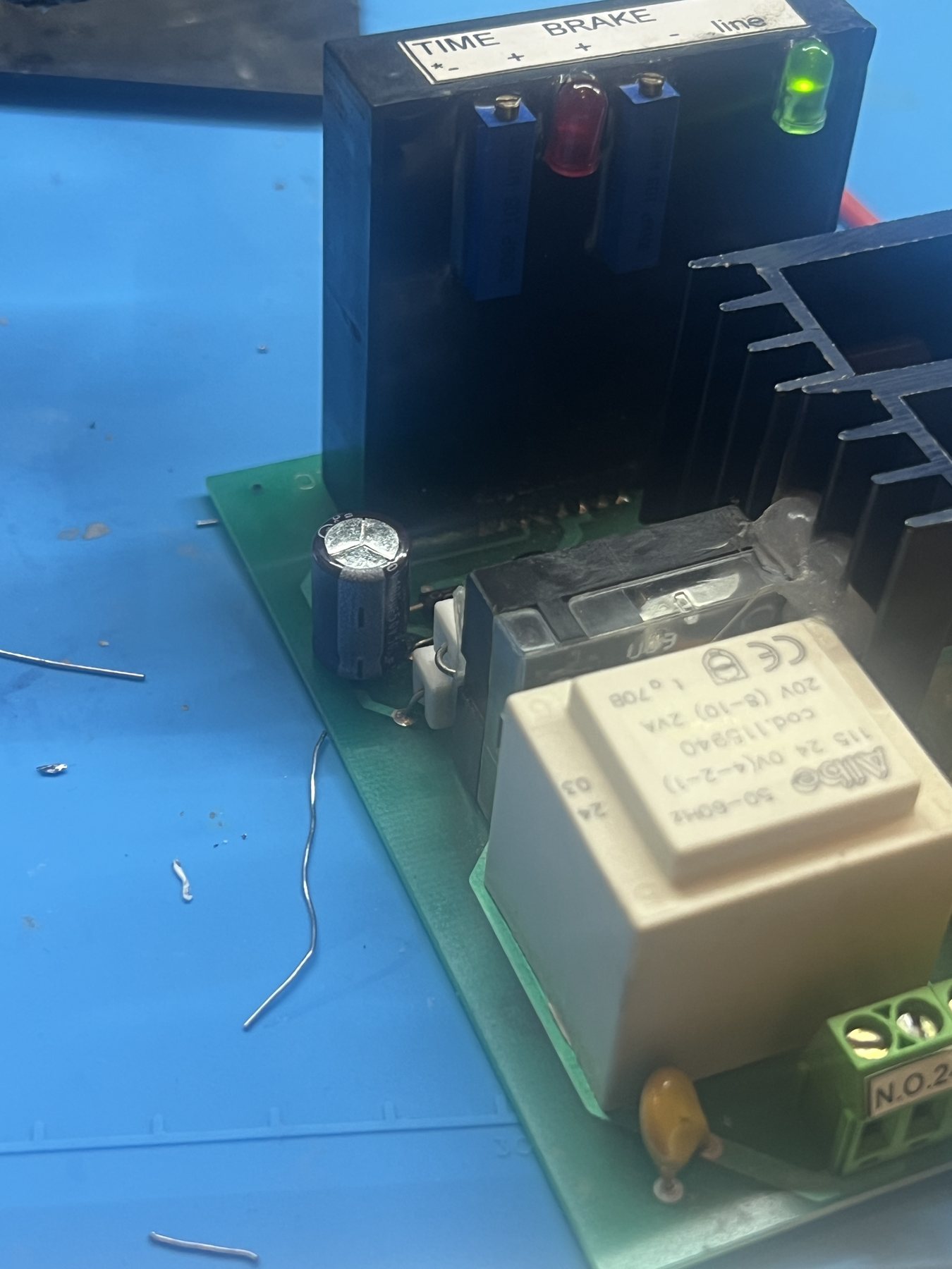
We replaced it with a 1000 uF, 100 V electrolytic capacitor we had available in the workshop. The result was immediate. The DC supply stabilised and the brake controller began operating normally every single time.
A tiny component causing a very large problem
The final failure was remarkably simple: one failed electrolytic capacitor in the low-voltage power supply. But that small component had taken an entire industrial food mixer out of normal operation.
Without repairing the original board, the alternative was approximately $2,000 for a replacement braking controller, followed by modification and retrofit work to install it into the existing machine.
Instead, the original controller could be repaired at component level and returned to service without redesigning the machine's braking system.
Why industrial electronics are worth repairing
Older industrial electronics should not automatically be discarded just because replacement boards are unavailable. A control board might contain relays, transformers, rectifiers, timers, and power semiconductors that are decades old, but the underlying electronics are often quite repairable.
Replacing an industrial controller is not always as simple as buying a new box. A retrofit can involve electrical modifications, new mounting arrangements, control wiring changes, interlock modifications, brake timing adjustments, and commissioning.
In this case, diagnosing and repairing the original controller avoided all of that. Sometimes the part responsible for shutting down a very large machine really can be a capacitor worth only a few dollars.
Job photos