PlayStation repair job
PS5 EDM-010 single beep, no light: diagnosing a blown F7502
This PlayStation 5 had an EDM-010 motherboard with a frustrating symptom: pressing the power button produced a single beep, but no blue light and no real startup attempt.
Initial symptoms
The console would:
- respond to the power button with a single beep
- show no blue or white light
- make no obvious attempt to fully power up
On a bench power supply, the board drew approximately 22 mA when 12 V was first applied.
Pressing the power button caused the current to drop slightly to around 20 mA, but there was no significant startup spike.
That suggested the board was alive enough to detect the power-button press, but the main power sequence was not progressing.
Checking the basics
I pulled the EDM-010 board and started with the usual checks.
All of the obvious fuses I initially tested had continuity:
- F7001
- F5401
- F5402
- F3501
The standby rails around the Southbridge were then checked.
I found:
- 5 V standby present
- 3.3 V present on one standby regulator
- 1.15 V present where expected
However, another rail labelled as 3.3 V standby in the reference material was only measuring approximately 1.78 V. That immediately looked suspicious.
Investigating the 1.78 V rail
Before doing anything to the suspect circuit, I measured a known-good regulator on the same board to establish a reference.
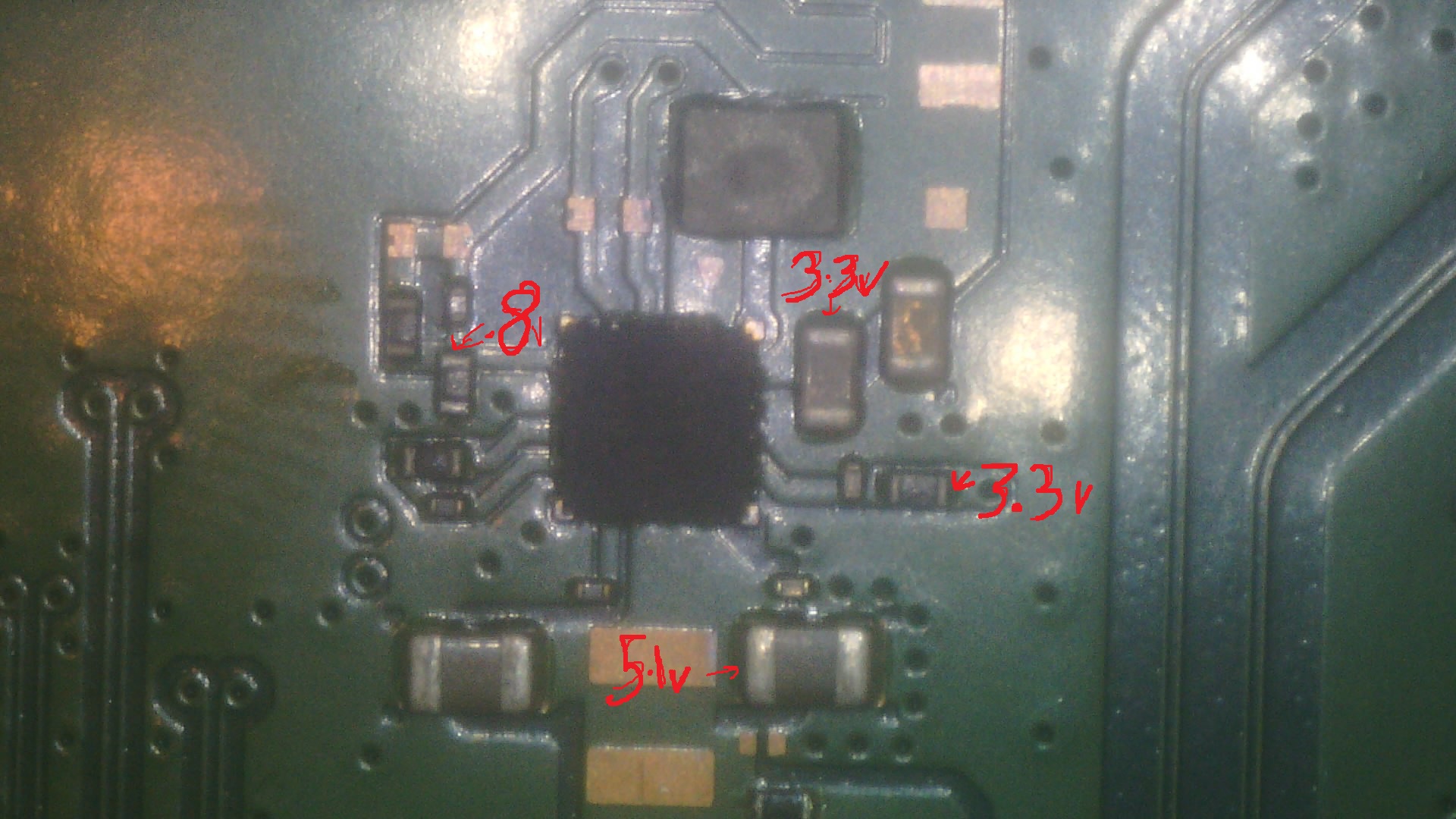
The known-good regulator was producing approximately:
- 5.1 V input
- 3.3 V output
- approximately 0.831 V on the feedback node
I also recorded resistance measurements around the known-good circuit so I had something useful to compare against.
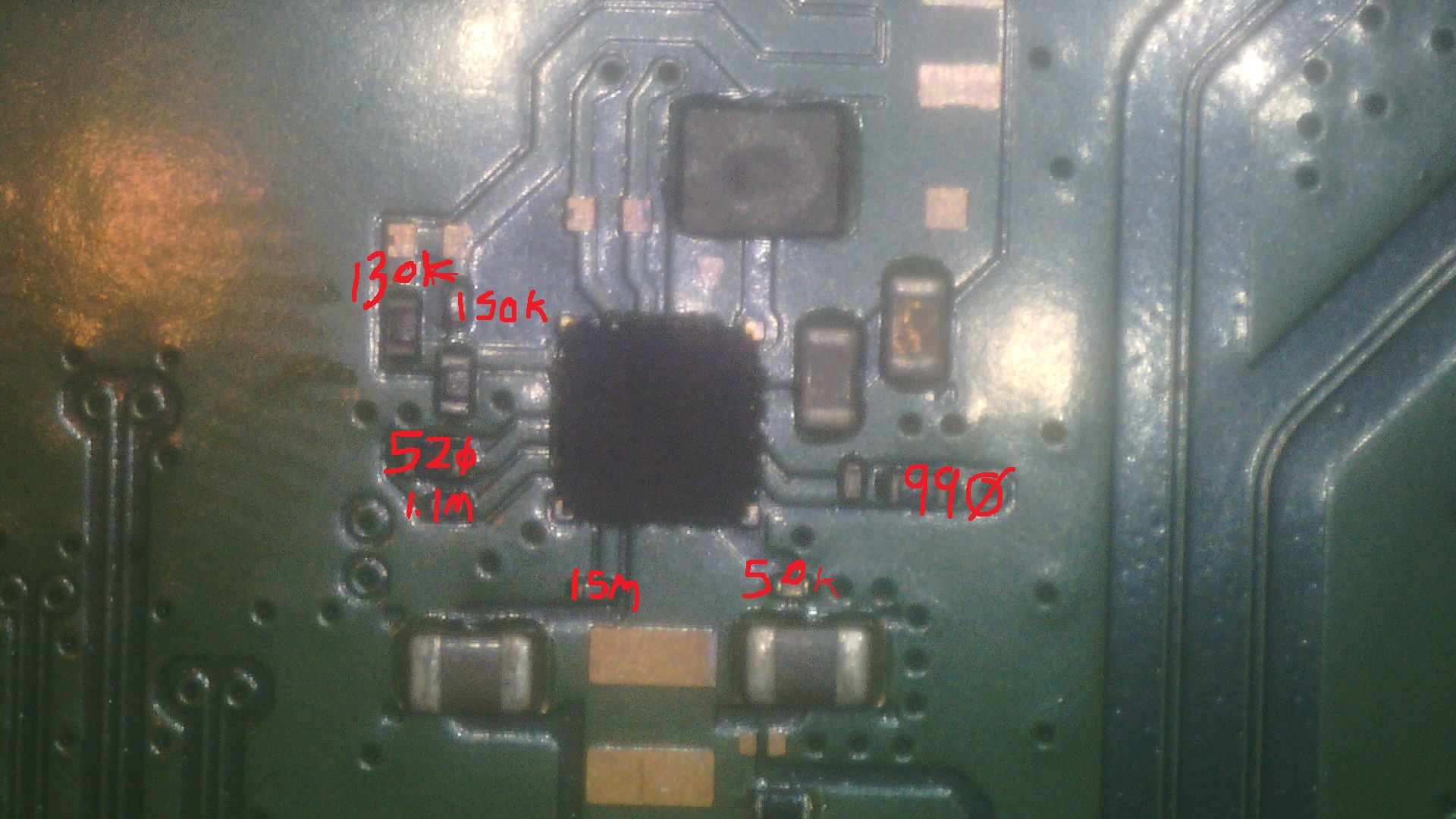
The suspect regulator had:
- approximately 5.1 V input
- only 1.7 to 1.8 V output
- approximately 0.831 V on the feedback node
At first, this made the regulator itself look like a likely failure. I replaced the regulator IC, but the output remained at approximately 1.7 V.
That ruled out the regulator IC itself as the obvious cause. The surrounding feedback resistors also measured normally, and diode-mode measurements between the good and questionable rails were fairly similar.
Isolating the suspect 3.3 V rail
To determine whether something downstream was loading the regulator, I lifted the output inductor.
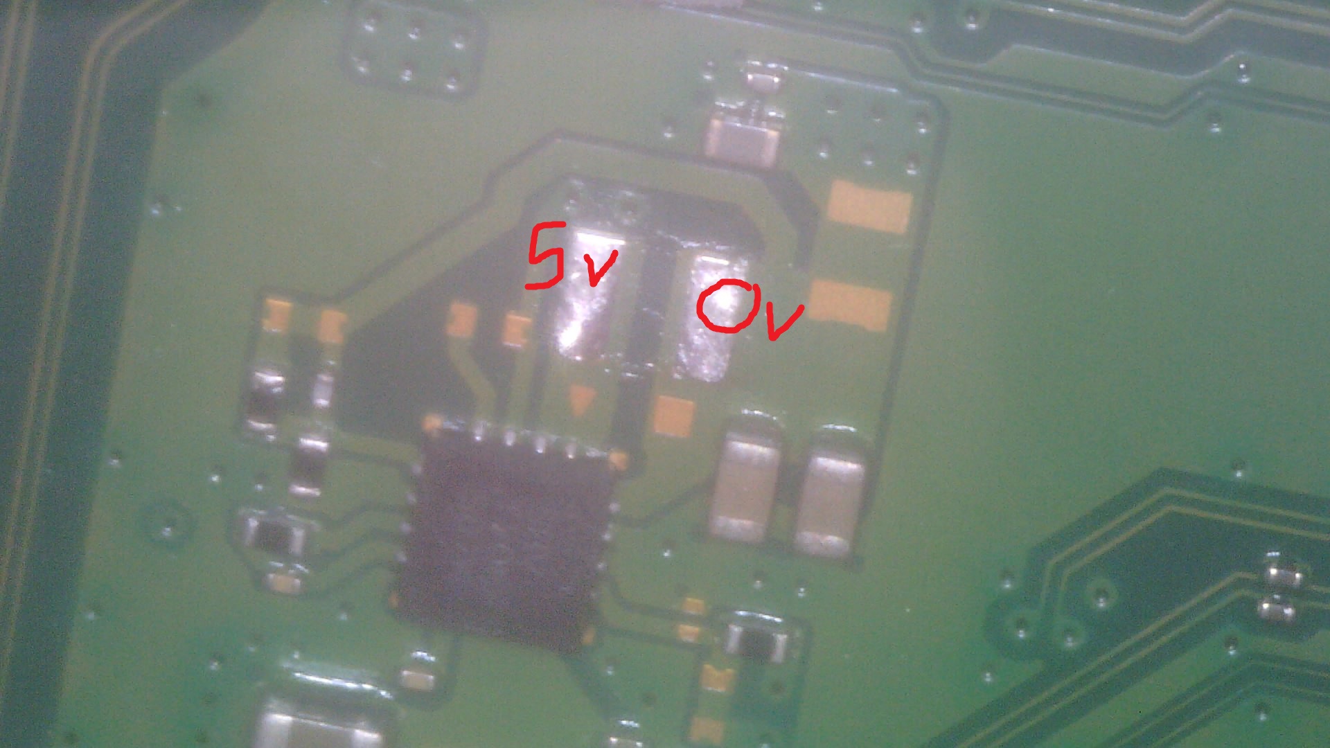
With the inductor removed, I could measure the regulator side and load side independently.
With 12 V supplied to the board, the regulator side rose to approximately 5 V, while the disconnected load side remained at 0 V, confirming the two sections were properly isolated.
I then checked both sides in diode mode.
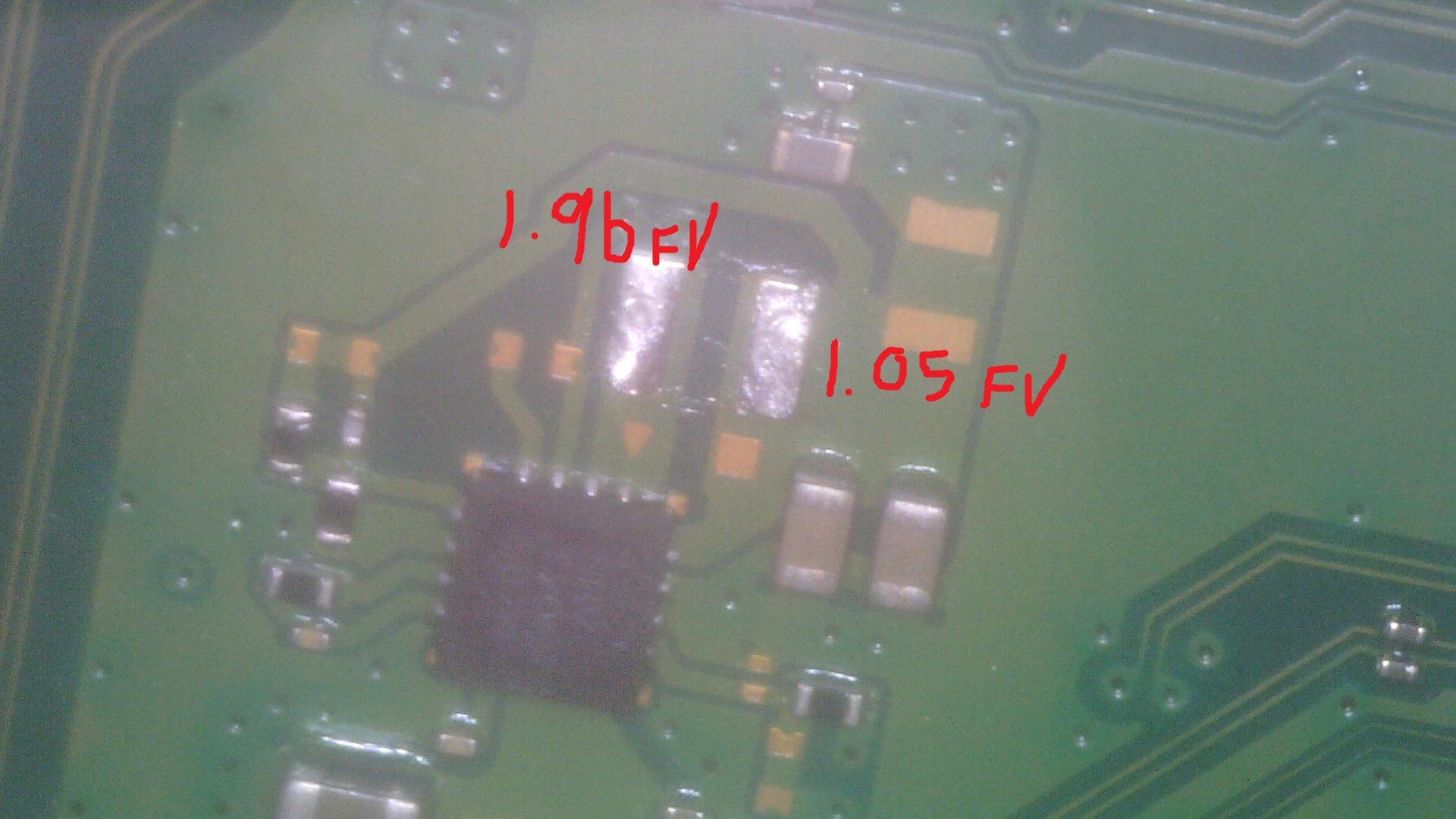
The readings were approximately:
- 1.96 V forward drop on one side
- 1.05 V forward drop on the other
I then measured resistance to ground.
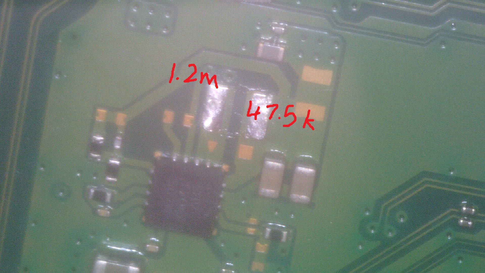
The regulator side measured approximately 1.2 M ohm, while the load side measured approximately 47.5 k ohm.
The lower resistance on the load side initially looked interesting, but it was nowhere near a hard short.
To test the rail under bias, I injected voltage directly into the isolated load side using a current-limited bench supply. At 1 V, there was essentially no current draw. At 3.3 V, the rail drew only around 29 mA.
That is less than 0.1 W of load and was nowhere near enough to explain a healthy 3.3 V regulator collapsing to 1.7 V. At this point, the supposed 1.7 V fault was looking less and less likely to be the actual reason the console would not boot.
UART changed the direction of the repair
Rather than continuing to chase the regulator circuit, I connected to the console through UART and read the stored error codes.
The important errors were:
80810001 - Severe
Power Sequence Error - General Power Failure
C0160203 / C0160303
HDMI to APU / Storage Controller related fault - Check Fuse F7502
That was the clue the repair needed. The generic power-sequence error by itself could have pointed almost anywhere, but the repeated storage-controller errors specifically referenced F7502.
F7502 was blown
I checked F7502 again and found that it was in fact blown.
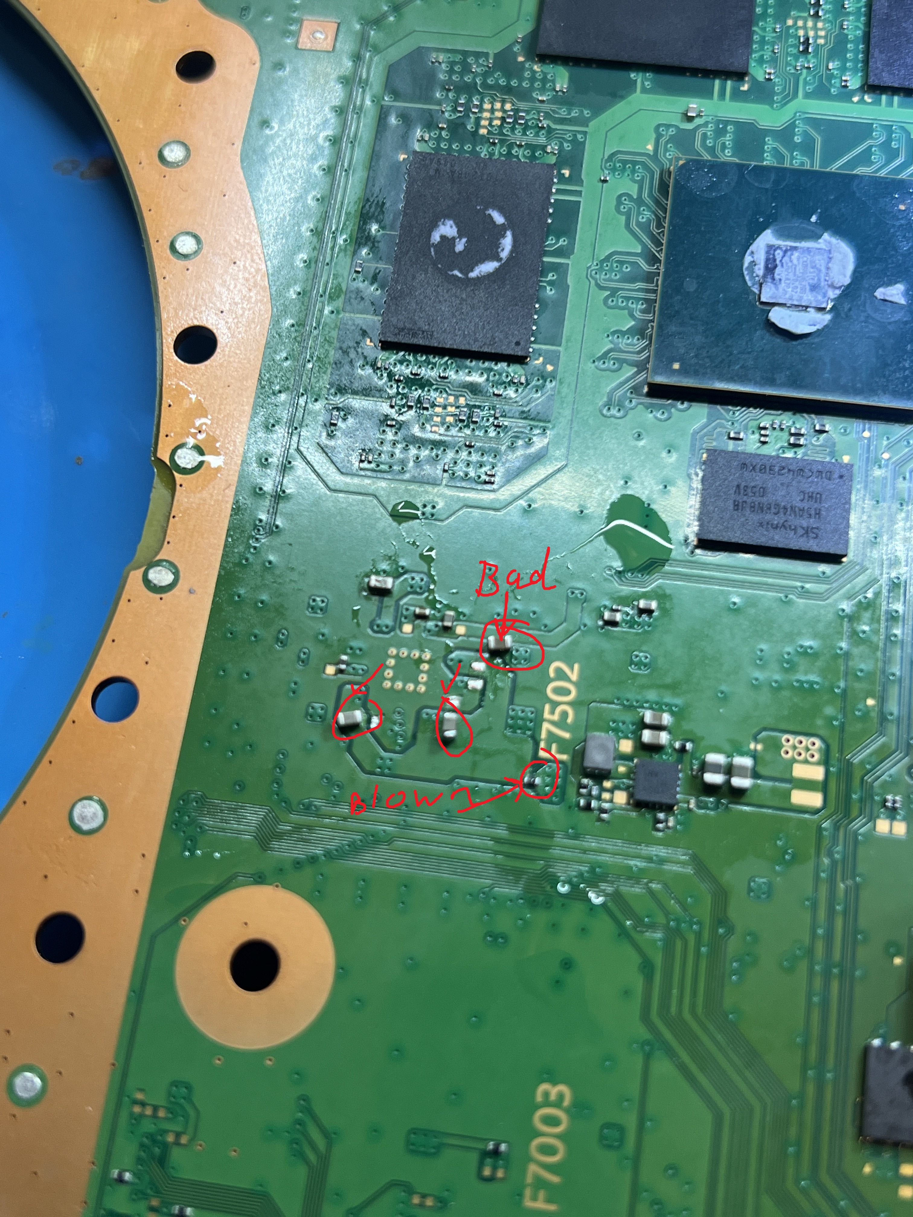
Even more importantly, there was a low-resistance condition on the load side of the fuse.
Injecting approximately 1 V into the load side produced more than 100 mA of current draw, confirming that something downstream of F7502 had likely caused the fuse to open.
At this point, the repair focus moved completely away from the earlier 1.7 V regulator and onto the storage-controller power rail.
The unexpected result
After voltage injection and another power cycle, I applied power to the board again.
This time, the PS5 powered on fully. The board completed its power sequence and booted normally.
So the actual failure path was tied to F7502 and the storage-controller rail, not the suspicious 1.7 V measurement that initially looked like the obvious fault.
What this repair taught me
This repair was a good reminder that a voltage which looks wrong is not automatically the cause of the boot failure.
The 1.7 V rail looked extremely suspicious because the reference material labelled the area as 3.3 V standby. I spent time comparing the regulator, swapping the IC, checking the feedback network, isolating the rail and performing voltage injection.
Those tests were still useful because they proved that the regulator and its load were unlikely to be responsible.
But the biggest breakthrough came from UART. The combination of single beep, no light, almost no change in current draw, 80810001, C0160203 and C0160303 led directly to the storage-controller circuit and F7502.
The final fault was a blown F7502 associated with an abnormal condition on its downstream rail. After isolating and testing that rail, the board recovered and successfully powered on.
Repair summary
- Console
- PlayStation 5
- Motherboard
- EDM-010
- Original symptom
- Single beep, no light, no startup
- Bench PSU standby draw
- Approximately 22 mA
- Initial misleading clue
- A supposed 3.3 V standby regulator measuring approximately 1.78 V
- Known-good regulator
- 5.1 V input, 3.3 V output, 0.831 V feedback
- Suspect regulator
- 5.1 V input, 1.7 to 1.8 V output, 0.831 V feedback
- Isolated load test
- Approximately 29 mA at 3.3 V
- UART errors
- 80810001, C0160203, C0160303
- Actual fault area
- Storage-controller power rail
- Failed component
- F7502 blown
- Result
- Console successfully powered on and booted
This one was a useful example of why UART belongs in the PS5 repair workflow. Basic measurements narrowed the problem down, but the error log stopped the repair from turning into an endless hunt across unrelated power rails.